Jun. 29, 2020
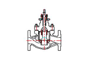
The shut-off valve refers to a valve with a leakage rate of less than 1/100,000, which is fast. It is a special regulating valve that only has a shut-off capability and no regulating effect.
The pneumatic membrane shut-off valve is a shut-off valve that uses compressed air as the power and membrane as the actuator. Structural accessories include air filter pressure reducer, valve positioner (generally cut-off valves do not have a valve positioner), solenoid valves, retention valves, valve position transmitters, valve position switches, etc. The shut-off valve cooperates with the detection instrument to prevent accidents. When the instrument detects a dangerous signal, the shut-off valve can act immediately to cut off the medium supply and prevent a malignant accident.
The difference between the shut-off valve and the regulating valve: The shut-off valve is a special kind of regulating valve, which only has two states of fully open and fully closed; the regulating valve can be adjusted arbitrarily in the range of 0~100%. Generally, the cut-off valve does not have a valve positioner, and the valve switch is controlled by the electrification and de-energization of the solenoid valve; the general regulating valve does not have a solenoid valve, and the valve opening degree is controlled by the valve positioner. The leakage of the shut-off valve is extremely small, and the main purpose of the regulating valve is to adjust the function, and the leakage is still large when it is fully closed.

Regulating Valve
notes
The usual pressure is actually pressured (force per unit area). The gauge pressure is usually used, that is, one standard atmospheric pressure in our living environment is used as the reference 0 pressure (reference point 0), and the difference with it is the gauge pressure value (usually the gauge used shows the gauge pressure value).
In fact, we live in an atmosphere of 1 atmosphere, and the value obtained by adding the gauge pressure to the absolute pressure is the absolute pressure value.
Standard atmospheric pressure actually has standard engineering atmospheric pressure at (kgf/cm2) and standard physical atmospheric pressure atm. The former was commonly used in the early years, but the latter is generally used now. 1atm=1.0332at=1.01325bar (bar)=101.325kPa=0.101325MPa.
The valve pressure mainly pays attention to two parameters: the rated working pressure value, such as PN16, indicates that the rated working pressure is 16bar (1.6MPa); the maximum allowable pressure difference value (the greater the value, the greater the thrust and torque of the actuator required to be equipped) .
notes
The structure and internal parts of the high-temperature valve and the normal-temperature valve are very different, such as the guide clearance, the valve plate rotation clearance, and the bearing method.
Ordinary positioning and guiding structures are unreliable for medium temperature above 400℃. At this time, the external bearing structure should be used to ensure the positioning and support of the valve plate, so as to avoid the influence of the internal high temperature on the guide structure.
The design and selection of the control valve used in the environment above 450 ℃ must consider the influence of temperature and pressure conditions on the mechanical strength of the material.
For applications above 538°C, the valve body usually uses chromium-molybdenum steel. For the highest temperature of about 1035℃, SUS310S stainless steel is usually selected, and the carbon content of the material must be controlled between 0.04 and 0.08%.
For higher temperatures, it is recommended to use non-metal heat-resistant materials lined (can be used in high-temperature occasions of 1200 ℃) or special high-temperature resistant high-strength alloys (such as high-temperature resistant high-strength alloys for engine combustion chambers, which can be directly used at 1000 ℃ High-temperature occasions).
Straight stroke regulating valve flow characteristics
The flow characteristic of the regulating valve is the relationship between the relative flow rate of the medium flowing through the regulating valve and its opening under the condition that the pressure difference across the valve is kept constant. The flow characteristics of the regulating valve are linear, equal percentage and parabolic. The significance of the three flow characteristics is as follows:
01
Equal percentage characteristics (logarithmic)
The relative stroke and the relative flow of the equal percentage characteristics are not in a linear relationship. At each point of the stroke, the change in flow caused by the unit stroke change is proportional to the flow at this point, and the percentage of flow change is equal. Therefore, its advantage is that when the flow rate is small, the flow rate change is small, and when the flow rate is large, the flow rate change is large, that is, it has the same adjustment accuracy at different openings.
02
Linear characteristics (linear)
The linear characteristics of the relative stroke and the relative flow have a linear relationship. The flow rate change caused by the change of unit stroke is constant. When the flow rate is large, the relative flow rate change is small, and when the flow rate is small, the relative flow rate change is large.
03
Parabolic characteristics
The flow rate changes in proportion to the two sides of the stroke, and generally has intermediate characteristics of linear and equal percentage characteristics.
From the analysis of the above three characteristics, it can be seen that in terms of its adjustment performance, the equal percentage characteristic is the best, and its adjustment is stable and the adjustment performance is good. The parabolic characteristic is better than the linear characteristic in adjusting performance, and any one of the flow characteristics can be selected according to the requirements of the use occasion.
Headquarter Add.: SUPCON Park, No.309 Liuhe Road, Binjiang District, Hangzhou, 310053, China.
Tel.: +86 571 8111 9774
Fax: +86 571 8111 9737
E-mail: [email protected]
