May. 25, 2020
4 Valve design to prevent cavitation
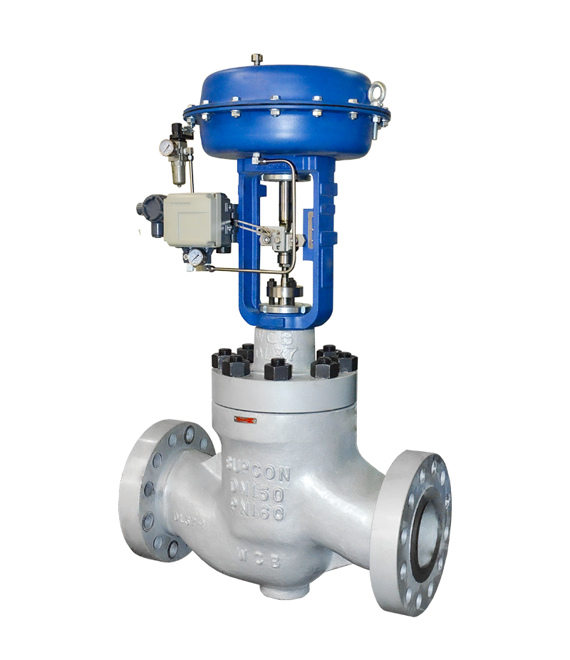
The structure of the corrosion resistance control valve affects its ability to prevent cavitation. Its main structural forms include tortuous paths, multi-stage decompression, enlarged flow area, and porous throttling design.
4.1 tortuous path
Passing the flow medium through a throttle containing a tortuous path is one way to reduce pressure recovery. Although this tortuous path can have different forms, such as small holes, radial flow paths, and so on. But the effect of each design is basically the same. This tortuous path is available in every component design that controls the occurrence of cavitation.
4.2 Multi-stage decompression
Each stage of the multi-stage decompression consumes part of the energy, making the inlet pressure of the next stage relatively low, reducing the pressure difference of the next stage, the pressure recovery is low, and the occurrence of cavitation is avoided. A successful design can make the globe control valve withstand a large pressure difference while still maintaining the contracted pressure higher than the saturation pressure of the liquid to prevent liquid cavitation. Therefore, for the same pressure drop, one-stage throttling is more prone to cavitation than multi-stage throttling.

Corrosion Resistance Control Valve
4.3 Expanding the flow area
Expanding the flow area is similar to the concept of multi-stage decompression. It is generally required that the throttling area of each stage is larger than that of the previous stage. The first stage of throttling withstands most of the pressure difference, and the pressure drop gradually decreases through continuous throttling. The pressure drop in the last-stage throttle area accounts for only a small percentage of the total pressure difference, so the pressure recovery is very small. If each stage is designed with equal throttle area and 10 stage throttle, then the pressure difference experienced by the last stage will only account for 10% of the total pressure difference, so even if the last stage produces cavitation, it will The intensity of cavitation damage caused is also minimal.
4.4 Porous throttle design
Porous throttling is a comprehensive design scheme. Each different orifice design affects the pressure recovery of the valve. The thin metal plate structure has the worst circulation efficiency, but the pressure recovery coefficient Km value is higher, which has a lower pressure recovery and is less likely to cause cavitation. The thick metal plate structure has higher circulation capacity, but the pressure recovery coefficient Km value is lower, which has higher pressure recovery and is prone to cavitation. The composite structure is the synthesis and balance of the first two designs. It not only has a higher flow capacity but also maintains a higher Km value, thus having a lower pressure recovery and avoiding the occurrence of cavitation. This design is the most typical and effective solution in flow capacity and cavitation control applications.
5 Summary
Cavitation and flashing are the most common flow phenomena in regulating valve devices. But through reasonable valve design can prevent the occurrence of cavitation, through the optimization of the valve structure and the reasonable selection of valve body materials can control the damage caused by flash evaporation.
Headquarter Add.: SUPCON Park, No.309 Liuhe Road, Binjiang District, Hangzhou, 310053, China.
Tel.: +86 571 8111 9774
Fax: +86 571 8111 9737
E-mail: [email protected]
